==> Page Back
AEI-CUSB0001
USB Internal Cable Assemblies
2x5 Keyed 9-Pin Female -to- 2x5 Keyed 9-Pin Female
Length is 12 inches
This is a custom cable assembly for AEI embedded PoE switches only. This cable assembly is used as a communications interface for PoE Advance Power Management features made available in the Fault Tolerant Utility and Command Line Interface.
This cable assembly has the +5VDC red wire clipped and electrically isolated.
Motherboard Connector Pinouts
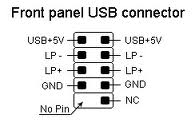
This assumes your motherboard has the following
internal USB 2.0 connector
and pinout:

Pin Header or Male Socket on the Motherboard
2x5 with Pin-9 blanked (or keyed)
2.54mm pitch pin-to-pin between row and column
WARNING:
The connector style and pinout on your
motherboard could be different than shown above. It is the
installer's responsibility to verify both connector style and pinout;
as well as proper installation of the internal USB cable assembly.
AEI is not responsible for damage caused by faulty cable
installations. If you use a 3rd Party cable assembly, AEI recommends clipping and electrically
isolating the red +5VDC wire on the AEI adapter side of the
termination (while system is powered off) to help avoid accidental
damage caused by a faulty cable installation. Always check for
proper cable installation prior to powering-up the system. If you
have a different pinout or connector style, please contact AEI for a
custom cable assembly quotation.
AEI Pinout
The AEI PoE adapter has a USB 2.0 1x4 pin strip
male header, 2.54mm pitch.
Pin 1 is designated on the PCB silkscreen.
| Pin # | Description | Wire Color |
| Pin 1 | No Connect | Red |
| Pin 2 | Data - | White |
| Pin 3 | Data + | Green |
| Pin 4 | GND | Black |
Pin1 on AEI USB connector is No Connect
The AEI embedded PoE controller does not use the +5VDC power, and as such this pin is a No Connect. Installers may install the red power wire to this pin, or this pin may be left floating. AEI cable assemblies come either with the red wire not installed, or clipped in order to help avoid accidental damaged caused by a faulty cable installation.
Cable Terminations
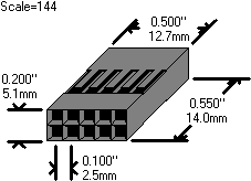
Each end of the cable has one 2x5 (pin 9 blanked) keyed female receptacle.

Either side of the 2x5 receptacle may be plugged into the 1x4 USB header on the AEI PoE embedded switch. Be sure to plug orientation is correct with Pin 1. The black wire (GND) must be connected to Pin 4 on the AEI header.
.jpg)